


CAN Bus Compatibility Testing for Commercial Vehicle LED Headlights
- CAN Bus compatibility is a vehicle-system decision
- Build a vehicle matrix before ordering samples
- Start with an installation and baseline inspection
- Test cold start, cranking and repeated key cycles
- Observe every commanded lighting mode
- Use dashboard messages and diagnostic data together
- Evaluate flicker without assuming every pulse is a CAN fault
- Check radio and electronic interference
- Bench tests clarify the electrical signature
- Verify thermal stability in the installed housing
- Keep optical performance separate from network acceptance
- Use a staged pilot instead of a fleet-wide first order
- Verified Carneon products for controlled evaluation
- H4 CAN Bus LED Headlight Bulb
- H7 CAN Bus LED Headlight Bulb
- N4 Plug-and-Play LED Headlight
- Write acceptance criteria before the sample arrives
- Prepare an RFQ that produces comparable answers
- Keep field service aligned with the approved configuration
- A defensible release sequence
- Frequently Asked Questions
Quick Answer: CAN Bus compatibility for a commercial vehicle LED headlight cannot be approved from a bulb label or a single successful installation. A fleet should validate the exact lamp, driver, connector, vehicle variant, control module, software level, voltage condition, and fault-detection behavior through a documented sample test. The acceptance plan should cover cold start, engine running, warning messages, flicker, dimming, radio interference, diagnostic trouble codes, thermal operation, and repeated key cycles. Carneon recommends a controlled vehicle matrix and pilot release before a retrofit kit is deployed across a mixed truck or bus fleet.
CAN Bus compatibility is a vehicle-system decision
A commercial vehicle does not judge an LED headlight only by whether the bulb illuminates. Its lighting controller may monitor current, pulse the circuit, store a diagnostic trouble code, command a fallback state, or display a warning when the electrical signature differs from the original lamp. The same retrofit can behave normally on one truck and produce warnings on another variant that looks identical from the outside. Procurement approval therefore belongs to the exact vehicle and electrical configuration, not to a general statement that a bulb is CAN Bus ready.
The term CAN Bus is often used loosely in lighting sales, although the bulb may not communicate directly on the vehicle network. In many installations, the relevant issue is how a body controller or lamp-monitoring circuit interprets current draw, voltage response, switching pulses, and fault conditions. A driver or external adapter may change that electrical behavior without becoming a network node itself. Buyers should ask what problem a proposed component is designed to solve and which vehicle evidence supports that claim.
Our current H4 and H7 CAN Bus product listings are published with a 9–32V input range, which makes them candidates for evaluation across several vehicle electrical systems. That published range does not prove compatibility with every truck, bus, van, controller, connector, or software release inside it. The N4 plug-and-play listing also covers several bulb formats and requires vehicle-level confirmation before approval. We treat those catalog facts as a screening point, followed by fit, electrical, optical, thermal, and diagnostic checks on the customer’s representative vehicles.
Build a vehicle matrix before ordering samples
A mixed fleet can contain several electrical architectures under one model name. Production year, trim, market, headlamp housing, original bulb wattage, connector, body controller, software calibration, daytime-running-light strategy, and optional lighting packages can all change the result. The sample plan should list each relevant combination and identify the number of vehicles that represent it. A single workshop vehicle should not be treated as proof for an entire national fleet when the purchase population contains untested variants.
The matrix should begin with identifiers that technicians can verify in the field. Useful fields include manufacturer, model, model year, vehicle identification range, market, system voltage, headlamp assembly reference, original bulb type, connector photographs, controller identification, and software level when accessible. The fleet should also record whether daytime running lights share the low-beam circuit or use pulse-width control. This information lets the supplier and buyer distinguish a repeatable compatibility issue from a one-off installation fault.
Sampling should include demanding and common configurations rather than only the easiest vehicle to access. An older truck with simple monitoring, a newer truck with sensitive lamp diagnostics, a bus with long duty cycles, and a vehicle that uses reduced-voltage daytime running may reveal different risks. If several body builders modify the same chassis, their harnesses and auxiliary systems may also need separate representation. The matrix becomes the boundary of the approval, so any untested variant remains pending rather than silently inheriting a pass.
| Matrix field | Evidence | Why it matters | Release decision |
|---|---|---|---|
| Vehicle variant | Model year, market and VIN range | Controllers can change within a model family | Approve only represented variants |
| Original lighting | Bulb, housing, connector and wiring record | Fit and load assumptions depend on the baseline | Match the correct sample format |
| Control behavior | DRL, dimming, warning and diagnostic strategy | Pulses and monitoring can expose incompatibility | Define functional test cases |
| Operating duty | Route, hours, vibration and ambient conditions | A workshop pass does not prove field stability | Set pilot duration and inspection |
Start with an installation and baseline inspection
Before installing a sample, the technician should confirm the original system operates correctly. Existing warning codes, voltage faults, corroded terminals, damaged connectors, moisture, weak grounds, nonstandard harness repairs, and mismatched bulbs can distort the result. The original lamp behavior should be recorded through several key cycles and operating modes. If the baseline is abnormal, the vehicle should be repaired or excluded until the fault is understood.
Physical fit is part of compatibility because a stressed connector or poorly retained driver can create electrical symptoms later. The bulb base must seat in the correct orientation, the retaining mechanism must close without force, and the heat sink or fan needs clearance inside the housing. Wiring should not contact sharp edges, hot parts, moving components, or the cooling fan. Dust caps and seals should retain their intended function without compressing the driver or bending the harness beyond a reasonable radius.
Polarity and connector engagement should be verified without improvised probing that damages terminals. Any supplied driver or approved adapter should be mounted according to the documented configuration, not left loose where vibration can move it. Grounds, supply voltage, and connector temperature deserve attention on older commercial vehicles because high resistance can mimic a lamp problem. The installation record should include photographs and the exact sample code so a later inspection can reproduce the setup.
Test cold start, cranking and repeated key cycles
A vehicle’s lighting circuit experiences changing voltage and control states during wake-up and engine start. A sample should be observed from a cold, rested condition with the engine off, during cranking where safe and appropriate, and after the charging system stabilizes. The technician should watch for delayed ignition, alternating lamp starts, momentary extinguishing, warning messages, audible relays, or repeated driver restarts. One clean start does not demonstrate repeatability, so the sequence should be performed several times under controlled conditions.
Low-temperature testing may be relevant when the fleet operates in a cold climate, but the required condition should come from the project specification rather than an invented universal limit. A cold electronic driver can respond differently from one already warmed by operation, while a cold battery can also change vehicle voltage during cranking. The test report should record ambient condition and vehicle battery state so the result is interpretable. A warning caused by a weak vehicle battery should not automatically be attributed to the LED sample.
Key-off behavior matters as well because some controllers continue diagnostic pulses after the driver leaves the cab. The fleet should observe whether a lamp flashes faintly, remains partially illuminated, or triggers repeated module activity after shutdown. Any observation needs to be compared with the original system and the vehicle’s normal sleep period. A retrofit that prevents a control module from sleeping or creates visible ghosting should remain unapproved until the system cause is resolved.

Observe every commanded lighting mode
The functional test should cover low beam, high beam, flash-to-pass, daytime running, automatic lighting, parking light interactions, and any dimming mode used by the vehicle. Combination bulbs such as H4 need special attention because both beam functions share one base and the vehicle may monitor them differently. Each command should produce a stable response on both sides without flicker or an unexpected delay. The technician should repeat the sequence with the engine stopped and running because supply and control behavior can change.
Pulse-width-controlled daytime running can expose behavior that is invisible at full command. A driver may flicker, buzz, cycle, run at an unintended brightness, or trigger a warning when it receives a pulsed supply. The fleet should assess that mode visually and electrically using qualified procedures, while avoiding unsupported changes to vehicle coding. If an adapter is proposed, it becomes part of the approved bill of materials and must be tested in the same location and thermal environment intended for production.
Automatic functions should be exercised through their normal sensors or service procedures rather than simulated with loose wires. Vehicles that turn lamps during steering, switch beams through a camera system, or use lighting during remote locking may add relevant test cases. The retrofit must not interfere with unrelated functions or generate intermittent warnings when commands change quickly. A pass should describe exactly which modes were tested, leaving untested options outside the approval.
Use dashboard messages and diagnostic data together
A dashboard without a warning is encouraging but does not prove the controller accepted the retrofit. Some vehicles store pending or history codes without showing a message, while others suppress a warning until several failed cycles occur. A qualified technician should scan the relevant modules before installation, clear only according to the approved service procedure, and scan again after the defined test sequence. The report should separate pre-existing codes from new codes and record their status rather than presenting a screenshot without context.
Diagnostic trouble codes should be interpreted using vehicle service information. A circuit code can result from load detection, wiring resistance, connector damage, voltage supply, a driver fault, or a control-module condition. Replacing an adapter repeatedly without diagnosing the circuit can hide the actual cause and create heat or reliability risks. The fleet should require a root-cause note for any code that appears during the pilot, even if the dashboard warning later disappears.
Warning behavior should be tested on both sides independently when the vehicle supports separate monitoring. Disconnecting one lamp under controlled service conditions may help verify whether the vehicle still detects a genuine open circuit, but such a test must follow the project’s safe procedure. A solution that simply masks every lamp fault can reduce maintenance visibility. Buyers should decide whether preserved failure detection is an acceptance requirement and document any limitation before fleet release.
Evaluate flicker without assuming every pulse is a CAN fault
Visible flicker can come from diagnostic pulses, pulse-width control, unstable supply, a poor ground, connector resistance, an incompatible driver, or a failing component. The observation should include when flicker occurs, which side is affected, whether the engine is running, and which lighting mode is active. A technician can then use suitable measurement tools to examine the circuit without guessing from appearance alone. Labeling every flicker event as a CAN Bus problem prevents accurate corrective action.
Camera recordings can help document a repeatable symptom, but rolling shutters can show bands that are not obvious to the eye. The fleet should combine visual inspection with electrical evidence and driver feedback where appropriate. A lamp that appears stable in a short workshop video may still behave poorly during voltage changes or long operation. Acceptance should therefore use several test methods and a defined observation period.
Adding a load component solely to suppress warnings needs engineering review because it can generate heat and waste power. Its resistance, power rating, mounting surface, wiring, enclosure, ventilation, and proximity to polymer parts all affect safety. An unmounted resistor hidden inside a lamp housing is not an acceptable fleet standard. If a validated external component is required, its part number and installation method should be controlled like any other electrical assembly.
Check radio and electronic interference
An LED driver switches current electronically and can become a source of conducted or radiated noise if the complete system is unsuitable. Commercial vehicles may carry AM/FM radio, fleet telematics, two-way radio, satellite equipment, cameras, navigation, sensors, and other electronics that deserve functional checks. The pilot should operate relevant equipment with the headlights off and on, across low and high beam, at idle, and at representative engine conditions. Any interference should be recorded by device, channel or operating mode, and location rather than described only as noise.
A quick radio check in one workshop is not a substitute for destination-market compliance evidence, but it can reveal a practical integration problem early. Cable routing, grounding, connector condition, driver location, antenna position, and auxiliary equipment can influence the observation. The fleet should avoid making ad hoc shielding or grounding changes that are not reviewed by qualified personnel. A reproducible issue needs a controlled corrective configuration and a repeat test on the affected vehicle variant.
Interference evaluation should also include vehicle communications and safety-related equipment that the operator considers relevant. Warning lamps, camera images, telematics events, or sensor faults that appear only when the headlight is energized need investigation before release. The test should not claim laboratory compliance from a field observation. It should state that the representative vehicle functions remained normal under the documented pilot conditions, with formal certificates reviewed separately when required.
Bench tests clarify the electrical signature
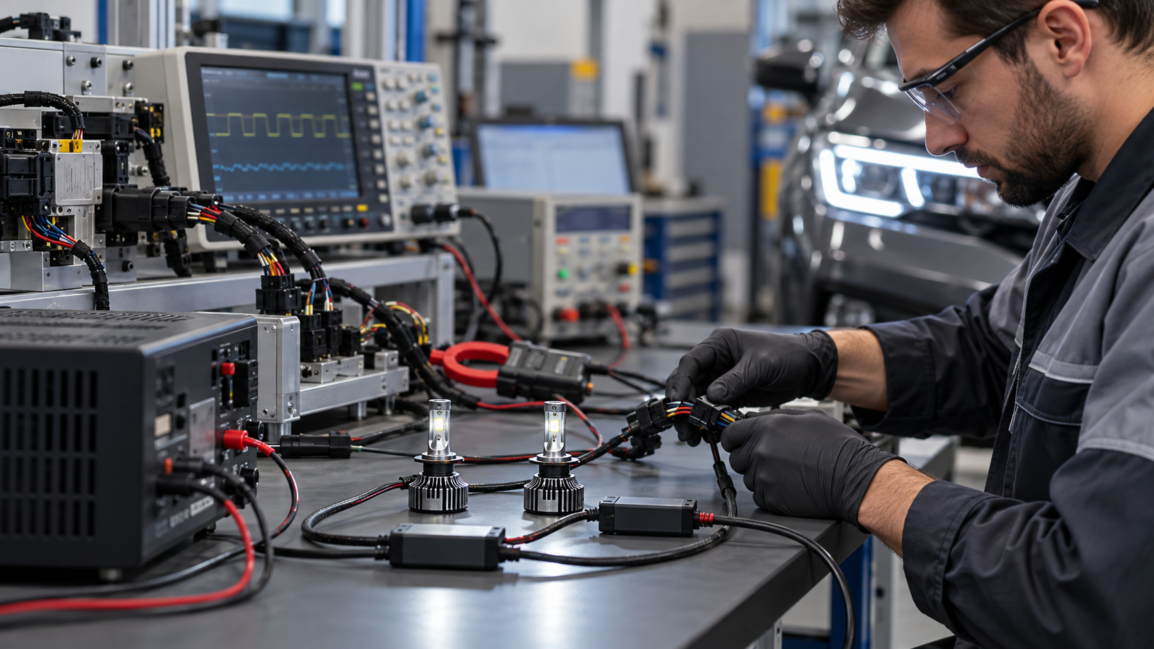
A controlled bench can compare current draw, start behavior, voltage response, driver stability, and switching behavior before a large vehicle trial. The setup should represent the intended system voltage and include suitable protection, calibrated instruments, correct connectors, and qualified operators. Measurements should cover steady operation and relevant transitions rather than a single current value. Bench evidence is especially useful when two vehicle variants react differently and the team needs to identify which electrical characteristic changed.
The bench does not reproduce every control-module algorithm, harness length, ground path, alternator condition, or diagnostic pulse used by a vehicle. Results should support the vehicle test rather than replace it. A driver that remains stable across a controlled supply range can still trigger a sensitive lamp monitor, while a sample that passes one truck may fail under a pulsed daytime-running command. The acceptance report should keep laboratory observations and vehicle-system conclusions clearly separated.
Sample identity and temperature should be controlled because electronic behavior can shift after warm-up. The engineer should record the bulb, driver, adapter, harness, input condition, operating time, and instrument method used for each result. If the proposed production configuration changes, the affected bench and vehicle tests need review. This traceability prevents a successful prototype with one driver revision from being used to approve a different mass-production assembly.
Verify thermal stability in the installed housing
Electrical compatibility can change as an LED driver and heat sink warm during operation. The fleet should run the lamps for a duration that represents the application and inspect stability, warning behavior, connector temperature, driver mounting, fan operation where present, and signs of heat exposure. Airflow around a bulb on an open bench differs from airflow inside a sealed commercial headlamp housing. A short functional check cannot establish thermal suitability for overnight driving.
Temperature assessment should use an agreed method and qualified limits rather than touch alone. The original housing, dust cap, harness, adapter, and nearby polymer parts should remain in their intended positions during the test. A component that requires the cap to remain open or the driver to hang outside the housing creates a different sealing and vibration condition. Such a workaround should not become a production installation unless the responsible parties have designed and validated it.
Thermal cycling can reveal intermittent connections or driver restarts that a continuous warm test misses. The pilot can include repeated on-off operation, vehicle shutdown and restart, and inspection after cooling. Any discoloration, odor, softened insulation, loose mount, abnormal fan sound, or connector deformation should stop the release and trigger investigation. Photographs and component identification should be retained so the supplier can examine the same configuration.
Keep optical performance separate from network acceptance
A retrofit can be electrically quiet and still produce an unacceptable beam. The LED emitter position, bulb orientation, headlamp optics, cutoff, glare, foreground light, high-beam aim, and mechanical retention need an optical assessment after installation. The headlamp should be aimed through the approved procedure and checked on suitable equipment or a controlled surface. A dashboard without warnings does not authorize a beam pattern that creates glare or reduces useful seeing distance.
Left-hand and right-hand traffic markets, reflector and projector housings, and different headlamp approvals can require separate evaluation. The same bulb format does not guarantee the same optical result in every housing. Fleet purchasing should treat electrical compatibility and road-legal suitability as independent gates, both of which must pass. Destination regulations and vehicle modification requirements should be reviewed by the responsible local party before deployment.
Driver feedback during a pilot can identify shadows, scattered light, poor sign visibility, or fatigue that a stationary check misses, but subjective reports need structure. The route, weather, load, speed, and comparison vehicle should be documented. Complaints should lead to an optical inspection rather than an immediate adjustment by untrained staff. Controlled aim and beam records protect both safety and consistency across the fleet.
Use a staged pilot instead of a fleet-wide first order
A staged release limits risk while creating useful evidence. The first stage can confirm fit and basic functions on one vehicle per matrix group, followed by a small pilot on vehicles that represent normal and demanding duty. The pilot should include defined operating hours, routes, inspections, driver reporting, code scans, and removal criteria. Only configurations with complete and stable records should move to a wider controlled rollout.
Pilot units need identifiers that link the vehicle, bulb, driver, adapter, installation date, technician, and inspection history. Without traceability, a replacement sample can enter the vehicle and make the result appear better or worse without explanation. Removed components should be quarantined with their fault record when investigation is required. This discipline also helps procurement distinguish an isolated damaged item from a configuration-wide incompatibility.
The rollout plan should preserve a hold point for unexpected warnings or field failures. A successful first batch does not justify mixing alternative drivers or locally sourced adapters when stock changes. Any substitution requires document review and, where the electrical behavior may differ, repeat testing. The approved bill of materials should reach purchasing, warehouse, installers, and service locations so every team uses the same configuration.
| Test stage | Required checks | Record | Hold condition |
|---|---|---|---|
| Baseline | Original lamps, codes, voltage and connectors | Vehicle baseline sheet | Unresolved pre-existing fault |
| Installation | Fit, retention, sealing, wiring and orientation | Photos and component IDs | Forced fit or unsafe routing |
| Functional | Modes, starts, warnings, codes and interference | Test-case results | New warning, flicker or fault code |
| Pilot | Duty hours, thermal behavior, beam and inspections | Vehicle service log | Repeatable field anomaly |
Verified Carneon products for controlled evaluation
Our active catalog includes CAN Bus-positioned H4 and H7 LED headlight bulb listings with a published 9–32V input range, plus the N4 plug-and-play family covering several bulb formats. These are relevant sample candidates for a commercial vehicle validation program, but the final part choice depends on the original bulb, housing, connector, duty, and vehicle matrix. We can review the buyer’s application data and prepare a controlled sample configuration. Unverified vehicle coverage should remain outside the quotation rather than being represented as universal compatibility.

H4 CAN Bus LED Headlight Bulb
An H4 sample candidate for dual-beam vehicle fit, control, warning, thermal and optical validation.
View Product
H7 CAN Bus LED Headlight Bulb
An H7 sample candidate for single-beam commercial vehicle compatibility and pilot testing.
View Product
N4 Plug-and-Play LED Headlight
A multi-format product family requiring confirmation of the exact base and vehicle configuration.
View ProductWrite acceptance criteria before the sample arrives
Acceptance criteria should state which vehicle variants, lighting modes, key cycles, voltage conditions, diagnostics, interference checks, thermal duration, beam checks, and pilot hours are required. Each item needs a clear pass, fail, or pending result supported by evidence. Vague language such as no problem found makes later disputes difficult to resolve. A pending result should block only the affected configuration while other independently verified variants can continue through their own review.
The document should also define who may install samples, operate diagnostic equipment, judge optical performance, and authorize a release. Procurement can coordinate evidence, but technical sign-off should remain with qualified responsible parties. Local legal and compliance review belongs in the plan where a retrofit changes an approved vehicle lighting system. The supplier’s product record, fleet test, and market approval are related evidence sets, not interchangeable claims.
Change control needs the same clarity as first approval. A new bulb revision, driver, connector, adapter, cable length, firmware, or manufacturing change can alter compatibility and should be reviewed against the approved baseline. The buyer and supplier should agree which changes require notification and which tests must be repeated. This keeps an initially successful program stable after several purchase batches and service replacements.
Prepare an RFQ that produces comparable answers
A useful RFQ identifies the vehicle matrix, destination markets, original bulb formats, system voltage, control functions, annual quantity, sample quantity, installation constraints, pilot plan, required documents, packaging, and acceptance method. It should ask the supplier to state exactly which variants have supporting evidence and which require testing. The RFQ should not invite a simple yes to universal CAN Bus compatibility. Clear boundaries produce quotations that purchasing can compare without relying on broad marketing language.
The buyer should request the current product specification, connector and dimension information, driver configuration, packing details, traceability method, and change-notification process for the quoted item. Where external adapters are proposed, their part number, mounting, wiring, heat management, and packaging need separate identification. Claims about certification, service life, or market coverage should be supported by current documents relevant to the delivered configuration. Unsupported values should be removed from the commercial comparison rather than treated as equivalent evidence.
Commercial review should include sample work, installation labor, diagnostic time, pilot vehicles, adapter control, spare policy, training, field inspection, and fault investigation. The lowest bulb price may not be the lowest project cost if warnings, radio noise, poor fit, or substitutions create repeated workshop visits. A controlled compatibility program makes these costs visible before a full deployment. It also gives the supplier a precise target instead of asking one component to solve every unidentified vehicle problem.
Keep field service aligned with the approved configuration
Installers should receive a vehicle-specific work instruction showing the approved bulb, driver, adapter where applicable, orientation, mounting point, cable route, sealing method, and post-installation checks. Generic packaging instructions cannot capture every fleet decision. Technicians should record component identities and stop when the vehicle differs from the approved matrix. Local improvisation can turn a verified configuration into an untraceable electrical modification.
Service teams need a diagnostic path for warnings, flicker, intermittent operation, radio noise, overheating, moisture, and beam complaints. The path should start with baseline vehicle condition and installation evidence before replacing parts. Swapping drivers and adapters between vehicles without records can spread uncertainty and damage otherwise good components. Quarantined returns should retain vehicle, date, symptom, photographs, and diagnostic context for supplier analysis.
Warehouse control should prevent visually similar but electrically different kits from being mixed. Labels, bin locations, kit contents, revision status, and vehicle applicability should match the approved bill of materials. Returned or superseded stock needs a defined disposition rather than re-entry into available inventory. This is especially important when a fleet operates several voltage systems or bulb formats through the same service network.
A defensible release sequence
First, identify the exact commercial vehicles, original lighting systems, control functions, and duty conditions. Establish a healthy baseline, select the correct Carneon sample format, and document the installed components. Complete fit, key-cycle, mode, warning, code, flicker, interference, thermal, and beam checks on every matrix group. Keep any unresolved variant pending instead of extending an approval by assumption.
Second, run a traceable pilot on representative routes and inspect the lamps after meaningful service. Record driver feedback, diagnostic results, component condition, installation stability, and any environment that differs from the workshop. Investigate anomalies with controlled evidence and repeat the affected test after a validated correction. Release a wider batch only when the approved configuration remains stable and the product revision is frozen.
Finally, connect procurement, installation, warehouse, and service records to the same vehicle-specific bill of materials. Require change notification, preserve sample and pilot evidence, and recheck compatibility when the vehicle or lamp configuration changes. Buyers can send us the vehicle matrix, original bulb details, connector photographs, system voltage, and required pilot scope for a precise sample review. That process converts a vague CAN Bus claim into a repeatable fleet acceptance decision without pretending one label can cover every commercial vehicle.
Frequently Asked Questions
Does a CAN Bus LED headlight communicate directly with the vehicle network?
Not necessarily. In many retrofit applications, the practical issue is how the vehicle’s lighting controller interprets current draw, switching pulses and fault conditions. The exact bulb, driver, adapter and vehicle variant must be tested together.
Why can the same LED bulb work on one truck but show a warning on another?
Model year, market, body controller, software calibration, daytime-running-light strategy, original lamp load and wiring condition can differ. Approval should therefore be limited to the vehicle variants represented in the test matrix.
What should a fleet test before approving an LED headlight retrofit?
The test should cover fit, sealing, cold start, cranking, repeated key cycles, every lighting mode, dashboard warnings, diagnostic codes, flicker, interference, thermal operation, beam performance and a representative field pilot.
Can an external resistor or decoder solve every compatibility problem?
No. A load component may address a specific monitoring behavior, but it also creates heat and becomes part of the controlled installation. Its rating, mounting, wiring and vehicle evidence require engineering review.
How many vehicles should be included in a pilot?
There is no universal number. The pilot should represent every relevant electrical architecture and include common and demanding duty. Each model-year, market, controller or lighting configuration outside that matrix remains unapproved.
What information should buyers send when requesting samples?
Provide the vehicle make, model, year, market, system voltage, VIN range, original bulb type, connector photographs, headlamp housing details, daytime-running-light behavior, known warnings and the planned pilot scope.
Recommended for you

Commercial Vehicle LED Headlight Vibration and Water-Ingress Fleet Acceptance

Commercial Vehicle LED Headlight Thermal Management and Fleet Validation

24V LED Headlights for Commercial Vehicles: Compatibility and Fleet Validation

Commercial Vehicle LED Headlight Beam Pattern and Glare Control
You May Also Like



Get More Resources
If you have any comments or good suggestions, please leave us a message, later our professional staff will contact you as soon as possible.
Start Your Wholesale Order / Request OEM Solutions
Partner directly with the factory for competitive pricing and priority support. Please provide your business details and estimated order volume (MOQ applies) so our sales engineers can tailor the best quote for your market.
Contact us


6th Floor, Building B, Liando U Valley, No. 29, Bishan Street, Huangpu District, Guangzhou, China

© 2026 CARNEON. All Rights Reserved. Privacy Policy | Terms and Conditions | Sitemap

Whatsapp: +8618688487142